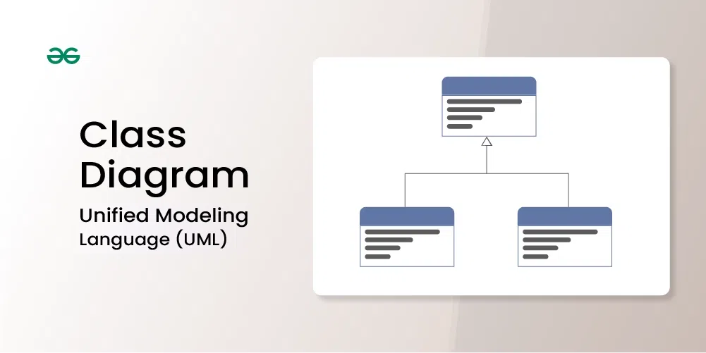
Class diagrams are a type of UML (Unified Modeling Language) diagram used in software engineering to visually represent the structure and relationships of classes in a system. UML is a standardized modeling language that helps in designing and documenting software systems. They are an integral part of the software development process, helping in both the design and documentation phases.

Important Topics for the Class Diagram
Class diagrams are a type of UML (Unified Modeling Language) diagram used in software engineering to visually represent the structure and relationships of classes within a system i.e. used to construct and visualize object-oriented systems.
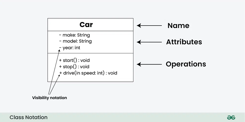
In these diagrams, classes are depicted as boxes, each containing three compartments for the class name, attributes, and methods. Lines connecting classes illustrate associations, showing relationships such as one-to-one or one-to-many.
Class diagrams provide a high-level overview of a system’s design, helping to communicate and document the structure of the software. They are a fundamental tool in object-oriented design and play a crucial role in the software development lifecycle.
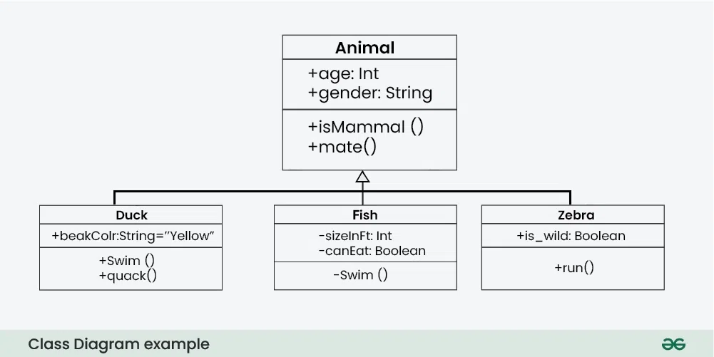
In object-oriented programming (OOP), a class is a blueprint or template for creating objects. Objects are instances of classes, and each class defines a set of attributes (data members) and methods (functions or procedures) that the objects created from that class will possess. The attributes represent the characteristics or properties of the object, while the methods define the behaviors or actions that the object can perform.
class notation is a graphical representation used to depict classes and their relationships in object-oriented modeling.
In class diagrams, parameter directionality refers to the indication of the flow of information between classes through method parameters. It helps to specify whether a parameter is an input, an output, or both. This information is crucial for understanding how data is passed between objects during method calls.
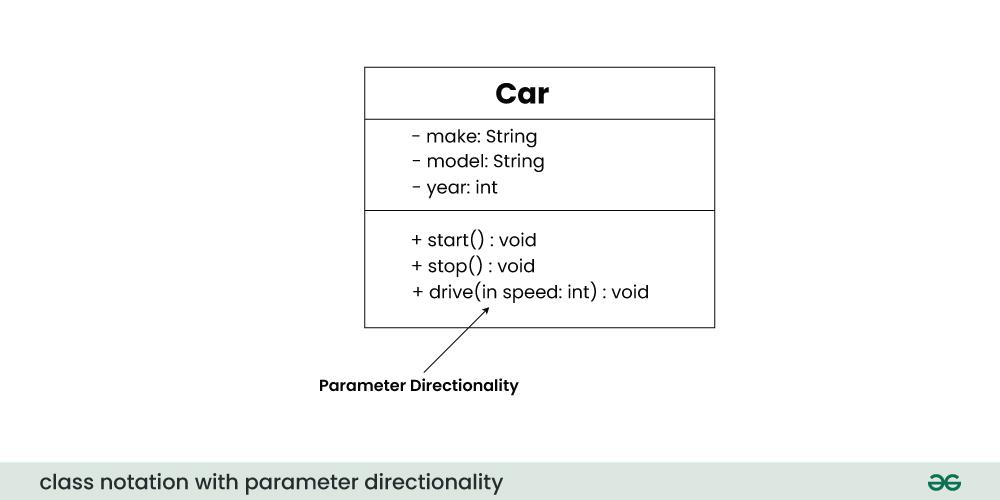
There are three main parameter directionality notations used in class diagrams:
In class diagrams, relationships between classes describe how classes are connected or interact with each other within a system. There are several types of relationships in object-oriented modeling, each serving a specific purpose. Here are some common types of relationships in class diagrams:
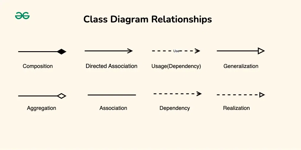
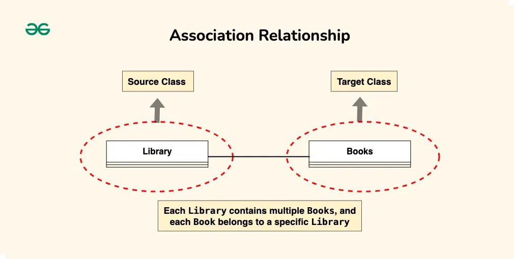
An association represents a bi-directional relationship between two classes. It indicates that instances of one class are connected to instances of another class. Associations are typically depicted as a solid line connecting the classes, with optional arrows indicating the direction of the relationship.
Let’s understand association using an example:
Let’s consider a simple system for managing a library. In this system, we have two main entities: Book and Library . Each Library contains multiple Books , and each Book belongs to a specific Library . This relationship between Library and Book represents an association.
The “Library” class can be considered the source class because it contains a reference to multiple instances of the “Book” class. The “Book” class would be considered the target class because it belongs to a specific library.
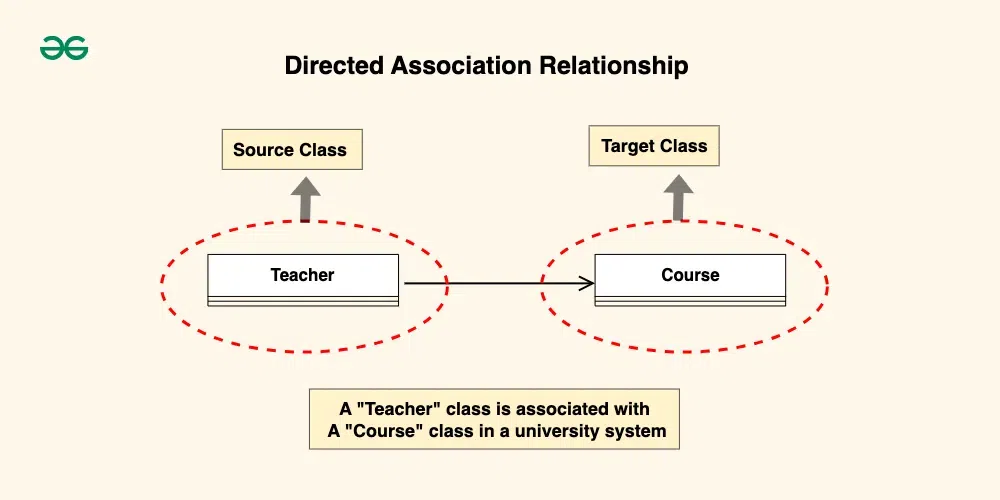
A directed association in a UML class diagram represents a relationship between two classes where the association has a direction, indicating that one class is associated with another in a specific way.
Consider a scenario where a “Teacher” class is associated with a “Course” class in a university system. The directed association arrow may point from the “Teacher” class to the “Course” class, indicating that a teacher is associated with or teaches a specific course.
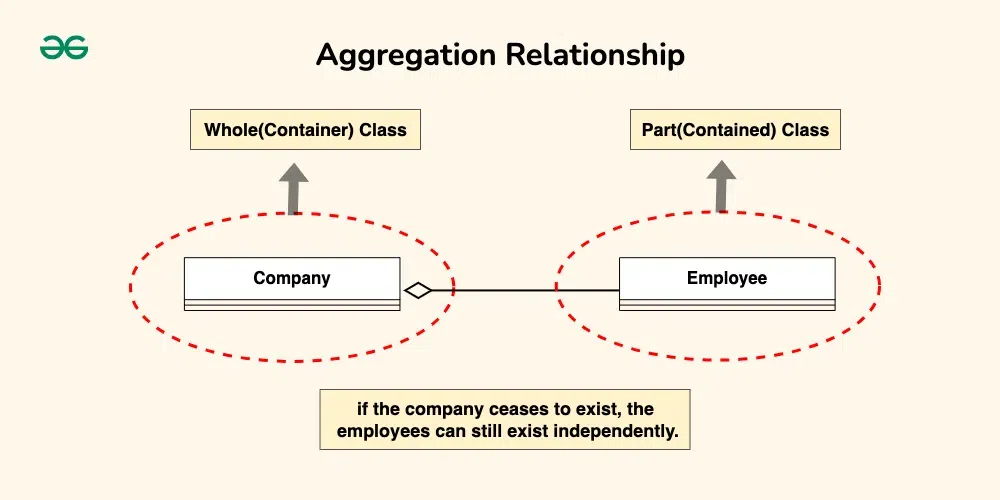
Aggregation is a specialized form of association that represents a “whole-part” relationship. It denotes a stronger relationship where one class (the whole) contains or is composed of another class (the part). Aggregation is represented by a diamond shape on the side of the whole class. In this kind of relationship, the child class can exist independently of its parent class.
Let’s understand aggregation using an example:
The company can be considered as the whole, while the employees are the parts. Employees belong to the company, and the company can have multiple employees. However, if the company ceases to exist, the employees can still exist independently.
Composition is a stronger form of aggregation, indicating a more significant ownership or dependency relationship. In composition, the part class cannot exist independently of the whole class. Composition is represented by a filled diamond shape on the side of the whole class.
Let’s understand Composition using an example:
Imagine a digital contact book application. The contact book is the whole, and each contact entry is a part. Each contact entry is fully owned and managed by the contact book. If the contact book is deleted or destroyed, all associated contact entries are also removed.
This illustrates composition because the existence of the contact entries depends entirely on the presence of the contact book. Without the contact book, the individual contact entries lose their meaning and cannot exist on their own.
.webp)
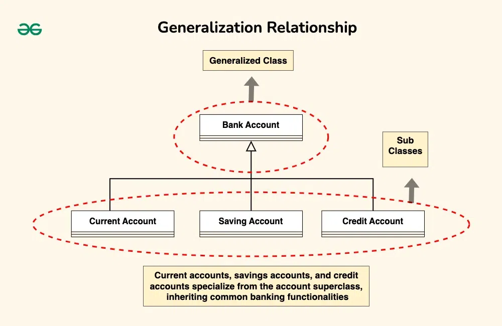
Inheritance represents an “is-a” relationship between classes, where one class (the subclass or child) inherits the properties and behaviors of another class (the superclass or parent). Inheritance is depicted by a solid line with a closed, hollow arrowhead pointing from the subclass to the superclass.
In the example of bank accounts, we can use generalization to represent different types of accounts such as current accounts, savings accounts, and credit accounts.
The Bank Account class serves as the generalized representation of all types of bank accounts, while the subclasses (Current Account, Savings Account, Credit Account) represent specialized versions that inherit and extend the functionality of the base class.
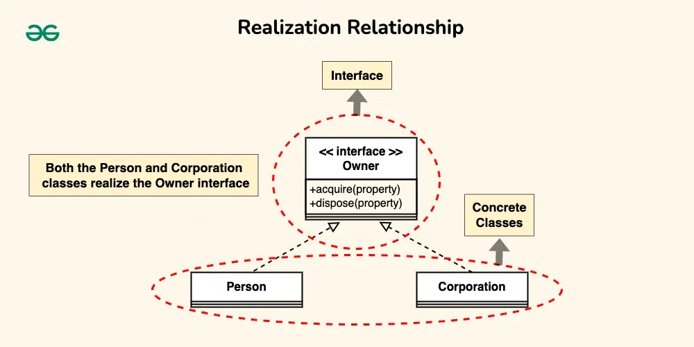
Realization indicates that a class implements the features of an interface. It is often used in cases where a class realizes the operations defined by an interface. Realization is depicted by a dashed line with an open arrowhead pointing from the implementing class to the interface.
Let’s consider the scenario where a “Person” and a “Corporation” both realizing an “Owner” interface.
Both the Person and Corporation classes realize the Owner interface, meaning they provide concrete implementations for the “acquire(property)” and “dispose(property)” methods defined in the interface.
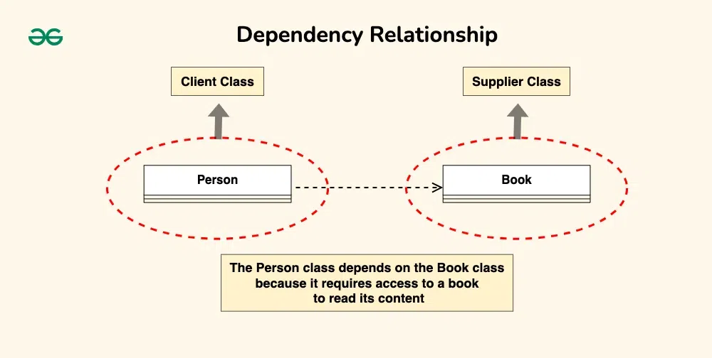
A dependency exists between two classes when one class relies on another, but the relationship is not as strong as association or inheritance. It represents a more loosely coupled connection between classes. Dependencies are often depicted as a dashed arrow.
Let’s consider a scenario where a Person depends on a Book.
The Person class depends on the Book class because it requires access to a book to read its content. However, the Book class does not depend on the Person class; it can exist independently and does not rely on the Person class for its functionality.
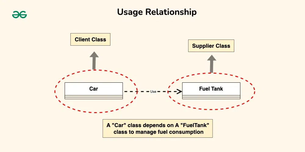
A usage dependency relationship in a UML class diagram indicates that one class (the client) utilizes or depends on another class (the supplier) to perform certain tasks or access certain functionality. The client class relies on the services provided by the supplier class but does not own or create instances of it.
Consider a scenario where a “Car” class depends on a “FuelTank” class to manage fuel consumption.
The main purpose of using class diagrams is:
Drawing class diagrams involves visualizing the structure of a system, including classes, their attributes, methods, and relationships. Here are the steps to draw class diagrams: